Surface Modeling

The image is the original surface.

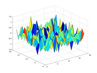
The image on the left is the above surface when noise is added. This surface is given as input to the program.
 Finally, the image on the left is the surface outputted from my program.
Well, if you cant make out the difference....and wondering what the hell is going on.... check out the images below...


The one on the top shows the difference in the noisy and the original surface...all spikes etc....yikes!!!
Wheras the one at the right is the difference in the surface outputted from the program and the original noise....no spikes...much smoother...which implies...o/p is much closer to original surface...
Yey!!!!
P.s: Dont care to ask if you didnt understand anything.
Cheers ;-)
